×
- Hello
- Login or Register
- Quick Links
- Live Chat
- Track Order
- Parts Availability
- RMA
- Help Center
- Contact Us
- Shop for
- Nissan Parts
- Nissan Accessories
My Garage
My Account
Cart
Genuine Nissan Quest Horn
Alarm Horn- Select Vehicle by Model
- Select Vehicle by VIN
Select Vehicle by Model
orMake
Model
Year
Select Vehicle by VIN
For the most accurate results, select vehicle by your VIN (Vehicle Identification Number).
14 Horns found


Nissan Quest Electric Low Horn Assembly
Part Number: 25620-8J000$146.21 MSRP: $225.29You Save: $79.08 (36%)Ships in 1-3 Business Days


Nissan Quest Electric High Horn Assembly
Part Number: 25610-ZB000$41.29 MSRP: $62.09You Save: $20.80 (34%)Ships in 1-3 Business Days

Nissan Quest Electric High Horn Assembly
Part Number: 25610-8J000$41.29 MSRP: $62.09You Save: $20.80 (34%)Ships in 1-3 Business Days
Nissan Quest Electric High Horn Assembly
Part Number: 25610-4AY0A$150.96 MSRP: $226.84You Save: $75.88 (34%)Ships in 1-2 Business Days
Nissan Quest Electric Low Horn Assembly
Part Number: 25620-1JA0A$162.58 MSRP: $244.29You Save: $81.71 (34%)Ships in 1-2 Business DaysNissan Quest Electric High Horn Assembly
Part Number: 25610-1JA0A$164.02 MSRP: $252.62You Save: $88.60 (36%)Ships in 1-2 Business DaysNissan Quest Electric Low Horn Assembly
Part Number: 25620-4AY0A$183.93 MSRP: $283.40You Save: $99.47 (36%)Ships in 1-3 Business Days
Nissan Quest Antitheft Horn Assembly
Part Number: 25605-1JA0A$150.28 MSRP: $225.82You Save: $75.54 (34%)Ships in 1-2 Business DaysNissan Quest Electric Low Horn Assembly
Part Number: 25620-ZB00A$146.21 MSRP: $225.29You Save: $79.08 (36%)Ships in 1-3 Business Days
Nissan Quest Electric High Horn Assembly
Part Number: 25610-ZB00A$40.30 MSRP: $62.09You Save: $21.79 (36%)Ships in 1-3 Business DaysNissan Quest Electric Low Horn Assembly
Part Number: 25620-ZB000$146.21 MSRP: $225.29You Save: $79.08 (36%)Ships in 1-3 Business Days

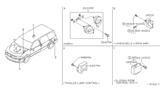

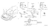
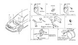
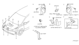
Nissan Quest Horn
The Nissan Quest Horn produces a fast, recognizable sound that lets other drivers know you're there and helps prevent accidents. Located at the front of the minivan, electrical energy from the steering wheel switch is converted to mechanical vibration of a diaphragm to produce the traditional honk or the sharper beep of newer versions. As both sound styles aim to serve the same objective, safety, they are quite different in tone. The previous Horn sounds, for example, have a lower note to cut through traffic noise. On the other hand, the later units have a higher sound that is better suited for busy city streets. It is a good thing for the Nissan family hauler that the Horn is required by law every model year as it can let others know when sightlines are lost behind trucks or heavy rain. If the unit fails, it is very easy to replace. The part itself typically costs under a reasonable amount depending on the Quest generation. Since the Horn is available either as a stand-alone emitter or as part of a complete assembly, owners can quickly return to proper functioning. This means that the Nissan safety signal, the Horn, keeps all Quest occupants and other road users in the know.
If you need any OEM Nissan Quest Horn, feel free to choose them out of our huge selection of genuine Nissan Quest Horn. All our parts are offered at unbeatable prices and are supported by the manufacturer's warranty. In addition, we offer quick shipping to have your parts delivered to your door step in a matter of days.
Nissan Quest Horn Parts Questions & Experts Answers
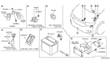
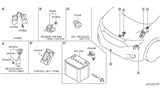
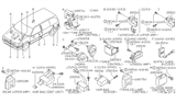
- Q: How to diagnose and replace Nissan Quest horns?A:Before beginning electrical diagnosis, check the Fuses. To access the horns, remove the left front inner fenderwell. Disconnect the electrical connector from the horns. To test the horns, connect battery voltage to the horn terminal using jumper wires; if either horn doesn't sound, replace it. If the horn does sound, check for voltage at the horn connector when the horn switch is depressed by connecting a voltmeter to the horn terminal and ground. If there's voltage at the connector, check for a bad ground at the horn. If there's no voltage at the horn, check the Relay. If the relay is functioning, check for voltage to the relay power and control circuits; if either circuit is not receiving voltage, inspect the wiring between the relay and the fuse panel. If both relay circuits are receiving voltage, depress the horn switch and check the circuit from the relay to the horn switch for continuity to ground. If there's no continuity, check the circuit for an open; if there's no open circuit, replace the horn switch. If there's continuity to ground through the horn switch, check for an open or short in the circuit from the relay to the switch. To access the horns for replacement, remove the left front inner splash shield from the fenderwell. Disconnect the electrical connectors and remove the bracket bolt to detach the horns. Installation is the reverse of removal.

