×
My Garage
My Account
My Cart
This part fits the vehicle you selected:
My Vehicle: 2002 Nissan Pathfinder Wagon; 6 Cyl 3.5L; Federal & California (From 20000120)
Change VehicleThe vehicle options this part fits:
- Production Date: 01/2000-05/2001
- Fitting Vehicle Options: VQ35DE + VG33E
Nissan 38164-0W060 Shaft Assy-Rear Axle
2000-2002 Nissan Pathfinder 381640W060
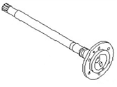

- Part DescriptionShaft Assy-Rear Axle
- Lookup Code38162
- PositionRear
- Replaced By38164-VE060
- ManufacturerNissan
- Require Quantity02
- Package Quantity1
This part fits the vehicle you selected:
2002 Nissan Pathfinder Wagon; 6 Cyl 3.5L; Federal & California (From 20000120)
The vehicle options this part fits:
- Production Date: 01/2000-05/2001
- Fitting Vehicle Options: VQ35DE + VG33E
$362.40 MSRP: $483.20 1
You Save: $120.80 (25%)
Ships in 1-3 Business Days
Product Specifications
| Brand | Genuine Nissan |
| Lookup Code | 38162 |
| Manufacturer Part Number | 38164-0W060 |
| Part Description | Shaft Assy-Rear Axle |
| Item Dimensions | 31.1 x 8.2 x 8.5 inches |
| Item Weight | 19.10 Pounds |
| Position | Rear |
| Condition | New |
| Fitment Type | Direct Replacement |
| Manufacturer | Nissan |
| SKU | 38164-0W060 |
| Warranty | This genuine Nissan part is guaranteed by Nissan's factory warranty. |
| Shipping & Return | Shipping Policy Return Policy |
Warning: California’s Proposition 65
Customer Questions & Answers
- Q:I want to make sure this part fits my car Posted by NissanPartsDeal Specialist
- A:You can Select Your Vehicle to check if 38164-0W060 fits your vehicle.Posted by NissanPartsDeal Specialist
- Q:How to replace and reinstall the rear axle shafts, Wheel Bearing, Wheel Seal in a Nissan Pathfinder? Posted by Customer
- A:Loosen the wheel lug nuts, raise the rear of the vehicle and support it securely on jackstands. Chock the front wheels to prevent the vehicle from rolling. Remove the wheel, brake drum and brake shoes, disconnect the parking brake cable from the lever on the trailing shoe and unbolt the cable casing from the backing plate, disconnect the hydraulic line fitting from the wheel cylinder, remove the nuts securing the axle retaining plate to the axle housing, connect a slide hammer and adapter to the axle flange and pull the axle from the housing, if the bearing or bearing grease seal must be replaced, take the assembly to an automotive machine shop to have the old bearing and seal removed and new ones installed, pry out the axleshaft oil seal with a seal removal tool and drive in the axleshaft oil seal with a seal installer, wipe the bore in the axle housing clean, apply a thin coat of grease to the outer surface of the bearing, if working on a four-cylinder, 2WD Frontier or Xterra install any shims that were present during removal, guide the axleshaft straight into the axle housing, rotate the shaft slightly to engage the splines on the shaft with the splines in the differential side gear, install new axle retaining plate nuts and tighten them to the torque, check the axleshaft end play using a dial indicator, on four-cylinder, 2WD Frontier and Xterra models the end play should be 0.0008 to 0.0059-inch (0.02 to 0.15 mm) and on all other models the end play should be 0.0-inch (0.0 mm), the remainder of installation is the reverse of removal, check the differential lubricant level and add some, if necessary, bleed the brakes, install the wheel and lug nuts, lower the vehicle and tighten the lug nuts to the torque.Posted by NissanPartsDeal Specialist
- Q:What is the function and structure of the drive axles and CV joints in the front differential/axle system of a Nissan Pathfinder? Posted by Customer
- A:Power is transmitted from the front differential/axle to the front wheels through a pair of axle shafts, each with an inner end bolted to an axleshaft connected to the differential side gears and an outer end with a stub shaft splined to the front hub and bearing assembly. The inner ends of the axle shafts are equipped with sliding constant velocity (CV) joints, while the outer ends have “ball-and-cage" type CV joints. The boots should be inspected periodically for damage and leaking lubricant, and if either boot of an axle shaft is damaged, that axle shaft must be removed in order to replace the boot. Should a boot be damaged, the CV joint can be disassembled and cleaned, but if any parts are damaged, the entire axle shaft assembly must be replaced as a unit. Common symptoms of worn or damaged CV joints include a clicking noise in turns, a clunk when accelerating after coasting and vibration at highway speeds, and play in the CV joints and axle shafts can be checked by grasping each axle and rotating it in both directions while holding the CV joint housings.Posted by NissanPartsDeal Specialist
- Q:What is the description and functionality of the rear axle assembly and related components in the Nissan Pathfinder? Posted by Customer
- A:The rear axle assembly is a hypoid, semi-floating type which allows the outer rear wheel to turn at a higher speed than the inner tire when the vehicle goes around a corner. On 4WD models, a fully independent front axle assembly is used with a differential and a pair of drive axles, each with an inner and outer constant velocity (CV) joint. An optional locking limited-slip rear axle is also available which allows for normal operation until one wheel loses traction. A limited-slip unit is similar in design to a conventional differential, except for the addition of a pair of multi-disc clutch packs which slow the rotation of the differential case when one wheel is on a firm surface and the other is on a slippery one. Often, a suspected "axle" problem lies elsewhere, so it is important to do a thorough check of other possible causes before assuming the axle is the problem. Overhauling the differential isn't cost effective for a do-it-yourselfer, so any further work should be left to a qualified repair shop.Posted by NissanPartsDeal Specialist
- Q:How to remove and reinstall the front drive axle in a 4WD Nissan Pathfinder's front suspension system? Posted by Customer
- A:Loosen the wheel lug nuts, raise the front of the vehicle, and support it on jackstands. Remove the wheel. Remove the free-running hub, then remove the snap-ring from the axle shaft splines. The manufacturer recommends replacing the snap-ring with a new one whenever it is removed, but save the old one; it will be used for end play measurement purposes. Remove the skid plate, if equipped. Remove the axle shaft-to-axle shaft flange bolts. Have an assistant apply the brake as you loosen the bolts to prevent the axle shaft from turning. Separate the axle shaft from the axleshaft flange. Place a floor jack under the outer end of the lower control arm and raise it slightly. Separate the tie-rod end from the steering knuckle. Remove the cotter pin and loosen, but don't remove, the nut from the upper control arm ball joint. Break the steering knuckle loose from the ball joint by striking the steering knuckle boss where the ball stud passes through. Remove the nut and separate the upper control arm from the steering knuckle. Pull out on the knuckle and push the axle shaft through it, then maneuver the axle shaft out. Be careful not to stretch the brake hose and don't lose the thrust washer on the outer end of the axle shaft. For installation, inspect the needle bearing in the knuckle. If it shows signs of wear, replace it. If you install a new bearing, ensure it faces in the proper direction. Install the thrust washer on the axle shaft, if removed. The chamfer on the washer must face the center of the axle shaft. Lubricate the needle bearing in the steering knuckle with multi-purpose grease and also the axle shaft splines. Guide the axle shaft into position, pass the outer end through the knuckle, then reconnect the upper axle shaft through the ball joint to the steering knuckle. Tighten the nut and install a new cotter pin. Connect the inner end of the axle shaft to the axleshaft flange, install the bolts and tighten them. Connect the tie-rod end to the steering knuckle, tighten the nut, and install a new cotter pin. Install the snap-ring in the inner groove on the axle shaft. Using a dial indicator, measure the end play of the axle shaft in the hub. If the end play is satisfactory, remove the snap-ring, measure its thickness with a micrometer, and install a new one of the same thickness. If the end play isn't within the specified range, install a snap-ring of the proper thickness. Snap-rings are available in various thicknesses. Install the free-running hub assembly. Install the wheel and lug nuts. Lower the vehicle and tighten the lug nuts.For Pathfinder models, follow similar steps with some variations: After removing the wheel, pull off the hub cap. Before using pliers, move the cap off by driving a chisel between the cap and the drive flange, a little at a time. Remove the snap-ring from the end of the Axle Shaft, then unscrew the nuts and remove the drive flange from the hub. Remove the skid plate if present. Remove the Axle Shaft-to-axle shaft flange bolts with an assistant applying the brake. Separate the Axle Shaft from the axle shaft flange. Remove the three nuts and detach the ball joint from the control arm. Pull out on the knuckle, push the Axle Shaft through it, and maneuver it out. Be careful with the brake hose and the thrust washer on the Axle Shaft's outer end. For installation in Pathfinder models, inspect the needle bearing in the knuckle for wear, ensure the bearing's correct orientation, install the thrust washer on the Axle Shaft ensuring the chamfer faces the axle's center, lubricate the necessary parts, guide the Axle Shaft into position, and reconnect it. Ensure you connect the ball joint to the control arm, check the O-rings on the drive flange, and install the drive flange. Install the snap-ring in the groove on the Axle Shaft and measure its end play. Adjust the snap-ring if necessary, install the hub cap, and finalize with the wheel and lug nuts. Ensure the vehicle is lowered safely, and the lug nuts are tightened adequately.Posted by NissanPartsDeal Specialist
- Q:How to remove and reinstall the rear axle assembly in a Nissan Pathfinder? Posted by Customer
- A:Loosen the rear wheel lug nuts, raise the rear of the vehicle and support it securely on jack stands placed under the frame rails. Block the front wheels to keep the vehicle from rolling off the stands. Remove the rear wheels, position a jack under the rear axle differential housing, disconnect the driveshaft from the rear axle pinion flange, disconnect the shock absorbers at their lower mounts, disconnect the vent hose from the fitting on the axle housing and fasten it out of the way, unscrew the brake line fittings from the brake hose junction block, then unbolt the brake hose junction block from the axle housing, plug the hose to prevent fluid leakage, also disconnect the ABS wheel speed sensor electrical connector(s), if you're working on a Pathfinder or a 2WD Frontier model remove the brake drums and brake shoes, disconnect the parking brake cables from the actuating levers, then unbolt the cable casings from the brake backing plates, on all other models, disconnect the parking brake cables from the crank levers on the backing plates, unscrew the nuts from the spring U-bolts, remove the spring plates, on Pathfinder and Xterra models, unbolt the stabilizer bar brackets from the axle, remove the coil springs, then unbolt the suspension arms and Pan hard rod from the axle housing, lower the jack under the differential, then remove the rear axle assembly from under the vehicle, installation is the reverse of removal, tighten the U-joint strap bolts to the torque, tighten all suspension fasteners to the torque values, and bleed the brakes.Posted by NissanPartsDeal Specialist
- Q:How do you remove and reinstall the front axle assembly and related components in a Nissan Pathfinder's suspension system? Posted by Customer
- A:Raise the vehicle and support it securely on jackstands, then detach the vent hose from the differential housing. Mark the relationship of the driveshaft to the differential companion flange, then unbolt the driveshaft from the flange and support it with a piece of wire from the under body. Unbolt the inner ends of the drive axles and support them with pieces of wire from the under body. For Frontier and Xterra models, support the engine from above with an engine hoist or an engine support fixture, unbolt the engine mounts and raise the engine for clearance. Support the front axle assembly with a floor jack placed under the differential, then unbolt the differential and axle tube mounts from the front suspension cross member and remove the bolt from each end of the differential mounting member. For Pathfinder models, support the front axle assembly with a floor jack placed under the differential, then remove the mounting bolts from the support brackets at either end of the axle/differential assembly and slowly lower the assembly and remove it from under the vehicle. Installation is the reverse of the removal procedure, tightening the mounting fasteners securely, the driveshaft and drive axle fasteners to the torque and checking the differential lubricant level and adding some, if necessary, to bring it to the appropriate level.Posted by NissanPartsDeal Specialist
If you have any questions about this product, please don't hesitate to ask us. We will be happy to help you!
Why choose Nissan Parts Deal
- Dedicated Service
Your complete satisfaction is our #1 goal
- Lowest Prices
Best deals on genuine OE parts from dealerships
- Fast Delivery
Orders are processed and delivered promptly