×
- Hello
- Login or Register
- Quick Links
- Live Chat
- Track Order
- Parts Availability
- RMA
- Help Center
- Contact Us
- Shop for
- Nissan Parts
- Nissan Accessories
My Garage
My Account
Cart
Genuine Nissan 300ZX Brake Pedal
Brake Pedal Pad- Select Vehicle by Model
- Select Vehicle by VIN
Select Vehicle by Model
orMake
Model
Year
Select Vehicle by VIN
For the most accurate results, select vehicle by your VIN (Vehicle Identification Number).
5 Brake Pedals found

Nissan 300ZX Pedal-Brake
Part Number: 46520-01P15$58.90 MSRP: $81.20Limited AvailabilityYou Save: $22.30 (28%)
Nissan 300ZX Brake Pedal
The Nissan 300ZX Brake Pedal is a part that issues the stopping command. This is executed when the vehicle operator applies foot pressure, converting that foot pressure into hydraulic force that slows or brings the Nissan sports car to a halt. Every time the driver steps on the Brake Pedal, it pushes a master cylinder that builds hydraulic pressure to clamp the calipers or drums at each wheel, so the feel and response at the Brake Pedal is directly related to safety. Over thousands of trips, the pad's ribbed rubber surface wears away, and on early 300ZX models with five-digit odometers, the shiny Brake Pedal pad was often inspected by buyers for hidden mileage. When the ribs wear off, the surface gets slick, and a wet sole can cause slipping during a hard stop, so fitting a fresh pad restores grip, appearance, and driver confidence. The car was equipped with a standard suspended Brake Pedal assembly throughout the production run, but its owners could specify a different factory Nissan street-tuned pad, a complete replacement assembly for restoration, or a racing style unit that replicated the car's actual on-track setup. The differences between them were the pad texture and leverage ratio rather than the overall layout. The 300ZX's Brake Pedal always keeping a true 300ZX feeling is attractive thanks to this attention.
If you need any OEM Nissan 300ZX Brake Pedal, feel free to choose them out of our huge selection of genuine Nissan 300ZX Brake Pedal. All our parts are offered at unbeatable prices and are supported by the manufacturer's warranty. In addition, we offer quick shipping to have your parts delivered to your door step in a matter of days.
Nissan 300ZX Brake Pedal Parts Questions & Experts Answers
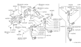
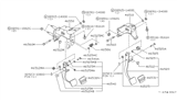
- Q: How are the switches attached to the brake pedal adjusted and checked for proper function on Nissan 300ZX?A:Two switches are mounted at the brake operational pedal adjacent to the fulcrum; the upper switch is the stop lamp switch while the lower one is the ASCD switch. The brake pedal free height can be adjusted removing the locknut from the booster input rod and turning the input rod till the free height matches the standard measurements and make sure the tip of the input rod is inside the booster. After finishing the tightening of the locking nut on the booster input rod, there should be a specific clearance between the two lever switches at the place where the tips of both the screws of the switches contact the brake pedal, and this clearance can be adjusted by loosening the locking nut in the switch and turning the adjusting nut, in case the clearance does not conform to the required standards. Also check/do the following: confirm that the free pedal travel is within standard/factory set values and check tat the stop lamp is out when the pedal is released. With the engine running, measure the brake pedal depressed height, i.e., check the distance from the face of the pedal to the floorboards and compare the result with the specified dimension; if the distance is less than the specified dimension, look for the signs of leakage, air accumulation or damages of hydraulic system components.


