×
- Hello
- Login or Register
- Quick Links
- Live Chat
- Track Order
- Parts Availability
- RMA
- Help Center
- Contact Us
- Shop for
- Nissan Parts
- Nissan Accessories
My Garage
My Account
Cart
Genuine Nissan 350Z Piston
Engine Pistons- Select Vehicle by Model
- Select Vehicle by VIN
Select Vehicle by Model
orMake
Model
Year
Select Vehicle by VIN
For the most accurate results, select vehicle by your VIN (Vehicle Identification Number).
13 Pistons found


Nissan 350Z Piston W/Pin
Part Number: A2010-8J110$88.44 MSRP: $130.82You Save: $42.38 (33%)Ships in 1-2 Business DaysNissan 350Z Piston W/Pin
Part Number: A2010-8J172$63.25 MSRP: $89.33You Save: $26.08 (30%)Ships in 1-2 Business Days
Nissan 350Z Piston,W/Pin
Part Number: A2010-JK22B$91.27 MSRP: $128.92You Save: $37.65 (30%)Ships in 1-2 Business DaysNissan 350Z Piston,W/Pin
Part Number: A2010-JK20B$150.39 MSRP: $212.42You Save: $62.03 (30%)Ships in 1-3 Business DaysNissan 350Z Piston,W/Pin
Part Number: A2010-JK21B$161.55 MSRP: $228.18You Save: $66.63 (30%)Ships in 1-3 Business DaysNissan 350Z Piston,W/Pin
Part Number: A2010-JK29B$177.11 MSRP: $250.15You Save: $73.04 (30%)Ships in 1-3 Business Days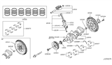
Nissan 350Z Piston
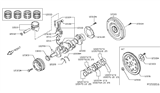
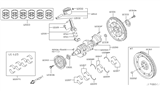
The Nissan 350Z Piston changes the combustion pressure into engine motion that eventually turns the crankshaft and propels the vehicle. Made of cast or forged aluminum alloy, the Piston is able to withstand high heat and pressure at a low weight. The Piston rings create a gas-tight seal between the Piston and the cylinder wall. This contains the expanding gases and controls the oil. A wrist pin connects the Piston to the connecting rod which converts the reciprocating motion to the crankshaft's rotating motion that then turns transmission gears, axle shafts, and wheels. The specifications of the component in terms of bore size, compression ratio, valve clearance, and pin style reflect the specifications found on the 350Z cylinder. Many versions feature surface coatings that prevent skirt scuffing, resist wear, and reflect heat to improve durability. All of the Nissan engines in the 350Z range rely on this precisely machined part, whilst its careful selection of material ensures that the Nissan sports car delivers reliable power throughout the entire Nissan 350Z range.
If you need any OEM Nissan 350Z Piston, feel free to choose them out of our huge selection of genuine Nissan 350Z Piston. All our parts are offered at unbeatable prices and are supported by the manufacturer's warranty. In addition, we offer quick shipping to have your parts delivered to your door step in a matter of days.
Nissan 350Z Piston Parts Questions & Experts Answers
- Q: What steps must be taken before removing the piston and connecting rod assemblies from the engine on Nissan 350Z?A:Before the piston and connecting rod assemblies are replaced, the cylinder head and oil pan have to be in particular taken out. First check for any ridges at the upper limit of ring travel in each cylinder and, if they have not been previously ground off, they should be removed with a ridge reamer to prevent piston failure. Once the ridges are gone, orient the engine with the Crankshaft vertical and measure and check the connecting rod end clearance with feelers that should fall to a specific range; if they do not, it may be necessary to replace connecting rods and pistons. Ensure you differentiate between the connecting rods and caps so that you do not confuse them; then undo the connecting rod cap bolts progressively till you can remove them by turning them with your fingers. To do so, remove the first connecting rod cap and bearing insert repeatedly and gently, and push the connecting rod and the piston assembly in the upward direction through the top of the automobiles' engine, making sure that all the ridges have been detached. Perform this for the rest of the cylinders and then place the caps and inserts back for shielding of the bearing surface. For piston ring installation make sure that the ring end gaps are correct, and the piston ring side clearance also. Place the oil control ring followed by the middle and the top rings though it is important to place the rings in the right manner. Before actually placing the piston assemblies, it is equally important that the cylinder walls and the edges in particular are thoroughly cleaned, and the crankshaft well positioned. New bearing inserts should be fitted without lubrication and should fit correctly and be positioned in the piston ring gaps. grease the piston then the rings; then, in a piston ring compressor, place the piston into the cylinder and oil the cylinder walls. Following the installation, verify the +oil clearance of the connecting rod bearing with Plastigage before fitting the cylinder and crankcase side. Always, where possible make sure the surface is clean of debris. If the clearance is out of permitted range, check the bearing sizes and the diameter of journal. Last, remove any Plastigage deposit over the bearings, relube the bearing surfaces with a grease, and tight the rod cap as in the previous process for all the assemblies, while being wary of cleanliness and orienting the thrusts in the correct form. Following that, turn the crankshaft in order to ensure that there are no signs of binding and, once again, verify the amount of end float of the connecting rod as this figure should not exceed the permissible limit.

Related Nissan 350Z Parts
 Nissan 350Z Crankshaft
 Nissan 350Z Crankshaft Pulley
 Nissan 350Z Crankshaft Thrust Washer Set
 Nissan 350Z Crankshaft Gear
 Nissan 350Z Alternator Bracket
 Nissan 350Z Belt Tensioner Bolt