×
- Hello
- Login or Register
- Quick Links
- Live Chat
- Track Order
- Parts Availability
- RMA
- Help Center
- Contact Us
- Shop for
- Nissan Parts
- Nissan Accessories
My Garage
My Account
Cart
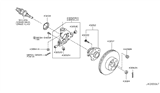
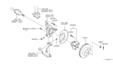
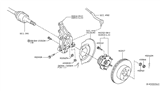
Genuine Nissan Murano Steering Knuckle
Front Steering Knuckle- Select Vehicle by Model
- Select Vehicle by VIN
Select Vehicle by Model
orMake
Model
Year
Select Vehicle by VIN
For the most accurate results, select vehicle by your VIN (Vehicle Identification Number).
18 Steering Knuckles found


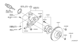
Nissan Murano Rear Axle Housing Assembly
Part Number: 43019-CN200$519.55 MSRP: $768.22You Save: $248.67 (33%)Ships in 1-2 Business Days


Nissan Murano Housing Assy-Rear Axle,RH
Part Number: 43018-CN200$519.55 MSRP: $768.22You Save: $248.67 (33%)Ships in 1-2 Business Days


Nissan Murano Spindle - KNUCKLE, LH
Part Number: 40015-CN000$598.75 MSRP: $885.33You Save: $286.58 (33%)Ships in 1-2 Business Days


Nissan Murano Knuckle Spindle-RH
Part Number: 40014-5AA0A$549.76 MSRP: $776.50You Save: $226.74 (30%)Ships in 1-3 Business Days


Nissan Murano Spindle - KNUCKLE, RH
Part Number: 40014-CN000$642.75 MSRP: $885.33You Save: $242.58 (28%)Ships in 1-2 Business Days
Nissan Murano Housing-Rear Axle,RH
Part Number: 43018-1AA0A$587.72 MSRP: $830.12You Save: $242.40 (30%)Ships in 1-3 Business Days
Nissan Murano Knuckle Spindle-RH
Part Number: 40014-5AA1A$549.76 MSRP: $776.50You Save: $226.74 (30%)Ships in 1-3 Business Days
Nissan Murano Housing Rear Axle RH
Part Number: 43021-1AA0A$476.33 MSRP: $672.78You Save: $196.45 (30%)Ships in 1-3 Business Days
Nissan Murano Knuckle Spindle-RH
Part Number: 40014-6SA0A$186.48 MSRP: $263.38You Save: $76.90 (30%)Ships in 1-3 Business Days
Nissan Murano Housing-Rear Axle,LH
Part Number: 43019-1AA0A$548.68 MSRP: $774.97You Save: $226.29 (30%)Ships in 1-3 Business DaysNissan Murano Knuckle Spindle-LH
Part Number: 40015-5AA1A$549.76 MSRP: $776.50You Save: $226.74 (30%)Ships in 1-3 Business Days
Nissan Murano Spindle-KNUCKLE,LH
Part Number: 40015-JP00A$521.62 MSRP: $736.75You Save: $215.13 (30%)Ships in 1-3 Business DaysNissan Murano Spindle-KNUCKLE,RH
Part Number: 40014-JP00A$521.62 MSRP: $736.75You Save: $215.13 (30%)Ships in 1-3 Business Days
Nissan Murano Housing Assy-Rear Axle,RH
Part Number: 43018-6SA0B$295.34 MSRP: $417.14You Save: $121.80 (30%)Ships in 1-3 Business Days
Nissan Murano Knuckle Spindle-LH
Part Number: 40015-5AA0A$549.76 MSRP: $776.50You Save: $226.74 (30%)Ships in 1-3 Business DaysNissan Murano Housing Rear Axle LH
Part Number: 43022-1AA0A$443.72 MSRP: $587.55You Save: $143.83 (25%)Ships in 1-3 Business Days
Nissan Murano Knuckle Spindle-LH
Part Number: 40015-6SA0A$186.48 MSRP: $263.38You Save: $76.90 (30%)Ships in 1-3 Business Days
Nissan Murano Rear Axle Housing Assembly
Part Number: 43019-6SA0B$316.31 MSRP: $446.77You Save: $130.46 (30%)Ships in 1-3 Business Days
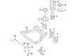
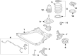
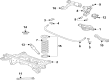
Nissan Murano Steering Knuckle
The Nissan Murano Steering Knuckle is one of the prominent parts which can explain the excellence of the brand. Steering Knuckle is an important component which joins the suspension system and the steering system by guiding the movement of the front wheels and providing better control and balance. Applicable to almost every Nissan Murano model, ranging from RWD to FWD, AWD or 4WD, the Steering Knuckle is a part dedicated to the improvement of the car's performance and safety. The cross-section gives firm places to connect to control arms, tie-rod ends, and the wheel hub and it enables the translated up and down and sideways in regards to road conditions. Progress in the Nissan Murano Steering Knuckle, the changes from kingpin to the modern ball joint models are worth noting, and they show a clear improvement of the automobiles' engineering. The Steering Knuckle should be inspected frequently for the proper running of the vehicle and its safety especially when, installing related parts. However, the highly pertinent product is the Nissan Murano Steering Knuckle, which distinguishes the car in the automotive market for its application of new material and design components, all of which ultimately affect the general driving experience. As known to be very efficient, the Nissan Murano Steering Knuckle is vital in contributing to the fact that Murano is one of the highly recommended mid-size SUVs in the market.
If you need any OEM Nissan Murano Steering Knuckle, feel free to choose them out of our huge selection of genuine Nissan Murano Steering Knuckle. All our parts are offered at unbeatable prices and are supported by the manufacturer's warranty. In addition, we offer quick shipping to have your parts delivered to your door step in a matter of days.
Nissan Murano Steering Knuckle Parts Questions & Experts Answers
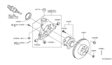
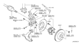
- Q: How to remove and install the rear Steering Knuckle of a Nissan Murano?A:Loosen the rear wheel lug nuts, then raise the rear of the vehicle and support it securely on jackstands while blocking the front wheels to prevent rolling. Remove the wheel, followed by the caliper and disc, and then the hub and bearing assembly. Next, remove the anchor block and the brake backing plate. Support the lower Control Arm with a floor jack positioned under the coil spring pocket. Detach the radius rod from the steering knuckle, and disconnect the front and rear lower suspension arms from the steering knuckle, ensuring the rear lower arm is supported by a floor jack while removing the fasteners. Disconnect the upper suspension arm from the steering knuckle by removing the cotter pin and using a balljoint separator to release the upper arm balljoint stud. Disconnect the lower shock mounting bolt and nut from the steering knuckle, then remove the steering knuckle from the vehicle. Installation is the reverse of removal, ensuring all fasteners are tightened to the specified torque, and before tightening the Radius Arm fasteners, lower arm-to-steering knuckle fasteners, and shock absorber lower mounting fasteners, raise the rear lower arm with the floor jack to simulate normal ride height.

Related Nissan Murano Parts


Browse by Year
2025 Steering Knuckle 2024 Steering Knuckle 2023 Steering Knuckle 2022 Steering Knuckle 2021 Steering Knuckle 2020 Steering Knuckle 2019 Steering Knuckle 2018 Steering Knuckle 2017 Steering Knuckle 2016 Steering Knuckle 2015 Steering Knuckle 2014 Steering Knuckle 2013 Steering Knuckle 2012 Steering Knuckle 2011 Steering Knuckle 2010 Steering Knuckle 2009 Steering Knuckle 2008 Steering Knuckle 2007 Steering Knuckle 2006 Steering Knuckle 2005 Steering Knuckle 2004 Steering Knuckle 2003 Steering Knuckle