×
- Hello
- Login or Register
- Quick Links
- Live Chat
- Track Order
- Parts Availability
- RMA
- Help Center
- Contact Us
- Shop for
- Nissan Parts
- Nissan Accessories
My Garage
My Account
Cart
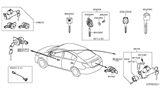
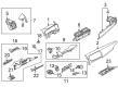
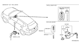
Genuine Nissan Rogue Ignition Switch
Starter Ignition Switch- Select Vehicle by Model
- Select Vehicle by VIN
Select Vehicle by Model
orMake
Model
Year
Select Vehicle by VIN
For the most accurate results, select vehicle by your VIN (Vehicle Identification Number).
11 Ignition Switches found


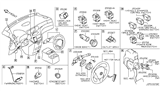
Nissan Rogue Ignition Switch
Part Number: 48750-0M010$65.35 MSRP: $92.30You Save: $26.95 (30%)Ships in 1-3 Business Days


Nissan Rogue Ignition Switch Assembly
Part Number: 25150-4BJ0A$64.85 MSRP: $93.92You Save: $29.07 (31%)Ships in 1-3 Business Days
Nissan Rogue Ignition Switch Assembly
Part Number: 25150-6LA1A$85.51 MSRP: $120.78You Save: $35.27 (30%)Ships in 1-3 Business DaysNissan Rogue Ignition Switch Assembly
Part Number: 25150-4BJ0C$64.85 MSRP: $93.92You Save: $29.07 (31%)Ships in 1-3 Business Days
Nissan Rogue Ignition Switch Assembly
Part Number: 48750-4BA0A$73.41 MSRP: $103.68You Save: $30.27 (30%)Ships in 1-3 Business Days
Nissan Rogue Switch Assembly - Vehicle Dynamics Control
Part Number: 25145-1KA0A$127.62 MSRP: $196.64You Save: $69.02 (36%)Ships in 1-3 Business Days
Nissan Rogue Ignition Switch Assembly
Part Number: 25150-7DA0A$70.62 MSRP: $102.28You Save: $31.66 (31%)Ships in 1-3 Business Days
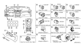
Nissan Rogue Ignition Switch Assembly
Part Number: 25150-4BA0A$103.12 MSRP: $149.35You Save: $46.23 (31%)Ships in 1-3 Business Days
Nissan Rogue Ignition Switch Assembly
Part Number: 25150-5HA0A$106.52 MSRP: $154.27You Save: $47.75 (31%)Ships in 1-3 Business Days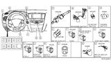
Nissan Rogue Ignition Switch Assembly
Part Number: 25150-4BC0C$77.99 MSRP: $112.95You Save: $34.96 (31%)Ships in 1-3 Business DaysNissan Rogue Ignition Switch Assembly
Part Number: 25150-4BC0A$77.99 MSRP: $112.95You Save: $34.96 (31%)Ships in 1-3 Business Days
Nissan Rogue Ignition Switch
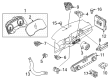
The Nissan Rogue Ignition Switch sends battery power to the primary vehicle circuits to start the engine, operate components, and lock the steering column when necessary. The Ignition Switch is mounted on the steering column and will accept a correctly coded key before the driver can rotate it through the lock, acc, on, and start positions. This sends a specific electrical current to the various components such as the starter motor, fuel injection system, and radio. In the lock position, the ignition key can be taken out, the steering wheel locks, and a shift interlock holds the transmission in park. When the key's on the start position, the Ignition Switch provides current to the starter and ignition circuits until the engine fires. Once the engine fires, the key can be turned on to the on position. This position maintains current to the driving functions. Acc powers features such as window operation without engine running. A faulty Nissan Rogue Ignition Switch that prevents cranking, causes the engine to turn off unexpectedly, or interrupts component power must be in proper condition to operate your Nissan Rogue. The installation of the correct Nissan Rogue Ignition Switch will restore electrical function.
If you need any OEM Nissan Rogue Ignition Switch, feel free to choose them out of our huge selection of genuine Nissan Rogue Ignition Switch. All our parts are offered at unbeatable prices and are supported by the manufacturer's warranty. In addition, we offer quick shipping to have your parts delivered to your door step in a matter of days.
Nissan Rogue Ignition Switch Parts Questions & Experts Answers
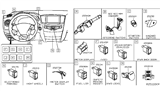
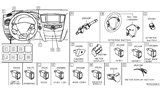
- Q: How to disconnect and replace the ignition switch and Ignition Lock Cylinder on Nissan Rogue?A:Remove the cable that is connected to the negative terminal among the cables connected to the terminals of the battery. Take off the screw cap from the steering column and take out the wiring connector of the ignition switch. Unscrew the ignition switch and extract it from the lock cylinder housing, but note that there is a tab that needs to be pushed to sever the electrical connection before pulling the ignition switch back out and unscrewing the retaining screws. But prior to installing the new switch, position the hub of the switch at the blade on the ignition lock cylinder. The rest of the installation process is done in the exact opposite order of the removal process, and then connect the battery before the required re-learn procedures are done. Illustration 27 calls for the withdrawal of the ignition switch, the separation of the shift-interlock cable from the ignition lock cylinder housing, and the withdrawal of the shear-head bolts to disengage the ignition lock cylinder from the steering column, although use may have to be made of a drill and screw-extractor. Removal and installation process involves the removal of the nuts from the shear-head bolts and covered with washers before being tightened to the brake-off point where the heads of the bolts bust off and reinstalling the battery, and final re-learn process. The first step is to take out the heating and air conditioning control assembly. Now with the help of a plastic trim tool one must retract the clips on the side panel and later on take it off the instrument panel. Pull out the connector of the electrical terminals starting with the push-button ignition switch in addition to prying the clips on the terminal on the NATS antenna amp so as to demount the switch from the ring of the NATS antenna amp. To get the NATS antenna amp ring off the panel, unlock the two locking tabs and pull the ring off the face of the panel. Installation is the process of putting back something removed in the opposite manner as it was done in removal.

Related Nissan Rogue Parts
 Nissan Rogue Brake Light Switch
 Nissan Rogue Ignition Coil
 Nissan Rogue Hazard Warning Switch
 Nissan Rogue Side Marker Light
 Nissan Rogue Turn Signal Switch
 Nissan Rogue Light Socket
 Nissan Rogue Dimmer Switch
Browse by Year
2025 Ignition Switch 2024 Ignition Switch 2023 Ignition Switch 2022 Ignition Switch 2021 Ignition Switch 2020 Ignition Switch 2019 Ignition Switch 2018 Ignition Switch 2017 Ignition Switch 2016 Ignition Switch 2015 Ignition Switch 2014 Ignition Switch 2013 Ignition Switch 2012 Ignition Switch 2011 Ignition Switch 2010 Ignition Switch 2009 Ignition Switch 2008 Ignition Switch