My Garage
Cart
Make sure this part fits

Nissan 13231-V5014 Lifter-Valve

1985-2004 Nissan 13231V5014

Customer Questions & Expert Answers (8)
13231-V5014 Nissan Lifter-Valve Product Photo 1 of 4
  • Part Description
    Lifter-Valve
  • Lookup Code
    13231
  • Replaced By
    13231-V5005
  • Manufacturer
    Nissan
Make sure this part fits
$212.03 MSRP: $299.48
You Save: $87.45 (30%)
Ships in 1-3 Business Days
1
ADD TO CART
  • Related Parts
  • Product Specifications
  • Vehicle Fitment
  • Customer Questions & Expert Answers
  • Product Specifications

    BrandGenuine Nissan
    Lookup Code13231
    Manufacturer Part Number13231-V5014
    Part DescriptionLifter-Valve
    Item Dimensions4.2 x 2.1 x 1.0 inches
    Item Weight0.40 Pounds
    ConditionNew
    Fitment TypeDirect Replacement
    Require Quantity12
    ManufacturerNissan
    SKU13231-V5014
    WarrantyThis genuine Nissan part is guaranteed by Nissan's factory warranty.
    Shipping & ReturnShipping Policy Return Policy
    Warning: California's Proposition 65
  • Vehicle Fitment

    Year Make Model Trim & Engine Important vehicle option details
    1986-1988 Nissan 200SXSGL|6 Cyl 3.0LVG30E
    1985-1989 Nissan 300ZXGL, GLL, SF, SS|6 Cyl 3.0LVG30, VG30T
    1998-2004 Nissan FrontierSC, SE, XE|6 Cyl 3.3LVG33E
    1986-1994 Nissan Hardbody Pickup (D21)DX, GST, ST|6 Cyl 3.0LVG30, VG30E
    1995-1997 Nissan Hardbody Pickup (D21U)Long Body SE, Long Body XE|6 Cyl 3.0LVG30E
    1989-1994 Nissan MaximaGXE, SE|6 Cyl 3.0LVG30E
    1987-2003 Nissan PathfinderLE, SE, ST, XE|6 Cyl 3.0L, 6 Cyl 3.3LVG30E, VG30I, VG33E
    1993-2003 Nissan QuestGXE, SE, XE|6 Cyl 3.0L, 6 Cyl 3.3LVG30E, VG33E
    2000-2004 Nissan XterraSE, XE|6 Cyl 3.3LVG33E, VG33ER
  • Customer Questions & Expert Answers

    Q:
    Will this part fit my car? Posted by NissanPartsDeal Specialist
    A:
    You can Select Your Vehicle to check if 13231-V5014 fits your vehicle.
    Posted by NissanPartsDeal Specialist
    Q:
    How to inspect and measure the Camshaft and Lash Adjuster components on the Nissan 300ZX? Posted by Customer
    A:
    Visually check the camshaft bearing surfaces for pitting, scoring, or any abnormal wear; if damaged, the head must be replaced. Measure the outside diameter of each camshaft bearing journal and record the measurements, then measure the inside diameter of each corresponding camshaft bearing tunnel with a vernier caliper and record those measurements. Subtract each cam journal outside diameter from its respective cam bearing tunnel inside diameter to compute the oil clearance for each bearing and compare the results to the specified journal to bearing clearance; if any measurements fail to meet standard wear limits, either the camshaft or the head, or both, must be replaced. Check camshaft runout by placing the camshaft between two V-blocks and setting up a dial indicator on the center journal, zeroing the dial indicator, and turning the camshaft slowly while noting the readings; if the measured runout exceeds the specified limit, replace the camshaft. Measure the camshaft cam lobe height with a micrometer, compare it to the specified height, and compute wear on the cam nose; if the wear exceeds the specified limit, replace the camshaft, repeating this for each cam lobe. Inspect the contact and sliding surfaces of each Lash Adjuster for wear or scratches, noting that if the Lash Adjuster pad is worn, the corresponding camshaft lobe may also be worn. Measure the outside diameter of each Lash Adjuster with a micrometer and compare it to the specified diameter; if worn beyond the limit, replace it, as Lash Adjusters can be purchased individually. Check each Lash Adjuster bore diameter in the Lash Adjuster guide assembly against the specified tolerance; if worn beyond the limit, the Lash Adjuster guide assembly must be replaced. Subtract the outside diameter of each Lash Adjuster from the inside diameter of its Lash Adjuster bore and compare the difference to the specified clearance; if both are within acceptable limits, this measurement should also fall within tolerance, but new Lash Adjusters or a Lash Adjuster guide assembly may affect this. Inspect the rocker arms and rocker shafts for abnormal wear and scratches, measure the outside diameter of the rocker arm shaft at each journal with a micrometer, and compare the measurements to the specified outside diameter. Measure the inside diameter of each rocker arm with either an inside micrometer or a dial caliper and compare to the specified inside diameter. Finally, subtract the outside diameter of each rocker arm shaft journal from its corresponding rocker arm inside diameter to compute the clearance and compare these measurements to the specified clearance; if any fall outside the limits, replace either the rockers or the rocker shaft, or both.
    Posted by NissanPartsDeal Specialist
    Q:
    How to remove and inspect the Lash Adjuster while preventing air from becoming trapped on Nissan 300ZX? Posted by Customer
    A:
    Take off the rocker arm cover and the rocker arm shaft assemblies in the Ford Escape hybrid. Tighten the lash adjusters by lifting them slightly and placing a rubber band on respective lash adjusters so that they do not fall out of the guides while being tightened; in case a lash adjuster drops off, place it in their respective guide. Take out the hydraulic lash adjuster guide assembly and thereafter take out each of the hydraulic lash adjusters from their holes, the arrangement of each lash adjuster must be the same as that of the bore it was removed from in order to be reinserted into the same location. Do not invert lash adjusters as this can admit air into them and this will call for bleeder. With this lash adjuster in the bore, apply a downward force on it to see if it shifts; if it does more than 1mm, there could be trapped air. If you think air is trapped, tighten the rocker arm and its cover and purge air from the lash adjuster for 10 minutes by advancing the engine and adding no load at 1,000 rpm. Then, take out the rocker arm cover and the rocker arm back and forward to listen for air; if air is present, replace the lash adjuster. When the lash adjusters are taken out, check for wearing signs on them. After the inspection is complete with the lash adjusters and other components, return the lash adjusters back to their bores, put back the rocker arm shaft assemblies and the rocker arm covers.
    Posted by NissanPartsDeal Specialist
    Q:
    How to remove and install the camshaft and lash adjuster on the 3.5L V6 Nissan Frontier? Posted by Customer
    A:
    The camshafts and Lash Adjusters should always be thoroughly inspected before installation and camshaft endplay should always be checked prior to camshaft removal. Detach the cable from the negative terminal of the battery. Remove the upper and lower intake plenums and the valve covers. Remove the timing chains and the camshaft sprockets. Remove the variable valve timing valve(s) from the top of the number one camshaft journal(s). Mark the camshaft bearing caps from 1 to 4, and with an "I" or an "E", to indicate intake or exhaust. Also mark arrows indicating the front of the engine. Loosen the camshaft bearing caps in two or three steps, in the reverse order of the tightening sequence. Remove the bearing caps and the camshafts. Make a note of the camshaft markings to ensure correct installation. Remove the Lash Adjusters and shims from the cylinder head, keeping the proper shim with each Lash Adjuster. Inspect the camshaft and Lash Adjusters. Lubricate the Lash Adjusters with clean engine oil, then install the Lash Adjusters and shims into their original locations. Apply moly-based engine assembly lubricant to the camshaft lobes and journals. Install the camshafts in their original positions with the dowel pins facing up and inline with the cylinder bank. Apply a bead of RTV sealant to the sealing surfaces of the No. 1 bearing cap(s) and the cylinder head. Install new O-rings on the secondary timing chain tensioner(s) and the VVT oil control orifice on the No. 1 bearing cap(s). Install the bearing caps and bolts and tighten them hand tight. Tighten the bearing cap bolts in several steps, to the specific torque, using the proper tightening sequence. Install the camshaft sprockets and timing chain. Hold the camshafts with a suitable wrench as you tighten the sprocket bolts to the specified torque. The remainder of installation is the reverse of removal. If any part of the valve train was replaced, check and adjust the valve clearance.
    Posted by NissanPartsDeal Specialist
    Q:
    Should the camshaft and lash adjuster be thoroughly inspected before installation on the Nissan Maxima with DOHC engine? Posted by Customer
    A:
    The camshafts and Lash Adjusters should always be thoroughly inspected before installation, and camshaft endplay should be checked prior to removal. Begin by detaching the cable from the negative terminal of the battery, then remove the valve covers. Next, remove the timing chains and camshaft sprockets; for 2004 and later models, unbolt the camshaft position sensor from the rear end of each cylinder bank if necessary, ensuring the working end of the sensor does not touch metal after removal. Mark the camshaft bearing caps from 1 to 4, indicating intake or exhaust with an "I" or "E," and mark arrows to show the front of the engine. Loosen the camshaft bearing caps in two or three steps, following the reverse order of the tightening sequence, while keeping the caps in order for reinstallation. Remove the bearing caps and camshafts, noting the camshaft markings for correct installation. Remove the Lash Adjusters and shims from the cylinder head, keeping the proper shim with each Lash Adjuster and maintaining their order for reinstallation. Inspect the camshaft and Lash Adjusters before proceeding with installation by placing the Lash Adjusters and shims back into their original locations. Apply moly-based engine assembly lubricant to the camshaft lobes and journals, then install the camshafts in their original positions with the dowel pins facing up and inline with the cylinder bank. Apply a bead of RTV sealant to the sealing surfaces of the No. 1 bearing cap(s), then install the bearing caps and bolts, tightening them hand tight before tightening the bearing cap bolts in several steps to the specified torque. Install the camshaft sprockets and timing chain, holding the camshafts with a suitable wrench while tightening the sprocket bolts to the specified torque. The remainder of the installation follows the reverse order of removal, and if any part of the valve train was replaced, check and adjust the valve clearance.
    Posted by NissanPartsDeal Specialist
    Q:
    What steps should be taken to inspect and measure the camshaft and lash adjuster for wear and damage on Nissan Quest? Posted by Customer
    A:
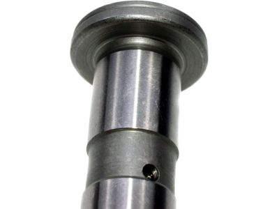
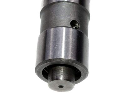
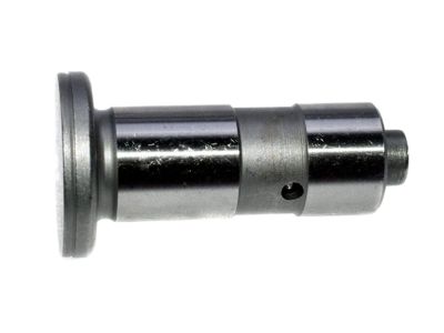
    Visually check the camshaft bearing surfaces for pitting, score marks, galling, and abnormal wear; if damaged, the cylinder head must be replaced. Measure the outside diameter of each camshaft bearing journal and record the measurements, then compare them to the specified journal outside diameter and measure the inside diameter of each corresponding camshaft bearing. Subtract each cam journal outside diameter from its respective cam bearing bore inside diameter to determine the oil clearance and compare the results to the specified journal-to-bearing clearance; if any measurements fall outside standard wear limits, replace the camshaft or the cylinder head, or both. Check camshaft runout by placing the camshaft between two V-blocks and setting up a dial indicator on the center journal, zeroing it, and turning the camshaft slowly to note the readings; if the measured runout exceeds the specified limit, replace the camshaft. Measure each cam lobe height with a micrometer, ensuring to get the highest reading, and compare it to the specified height, subtracting the measured height from the specified height to compute wear; if it exceeds the specified limit, replace the camshaft. Inspect the contact and sliding surfaces of each Lash Adjuster for wear and scratches, noting that if the Lash Adjuster pad is worn, the corresponding camshaft lobe should also be checked. Measure the outside diameter of each Lash Adjuster with a micrometer and compare it to the specifications; if any Lash Adjuster is worn beyond the limit, replace it. Check each Lash Adjuster bore diameter in the Lash Adjuster guide assembly and subtract the Lash Adjuster diameter to find the Lash Adjuster-to-guide clearance, comparing the results to the specifications; if any Lash Adjuster bore is worn beyond the limit, replace the Lash Adjuster guide assembly. Subtract the outside diameter of each Lash Adjuster from the inside diameter of the Lash Adjuster bore and compare the difference to the specified clearance; if both are within acceptable limits, this measurement should also fall within tolerance. Check the rocker arms and shafts for abnormal wear, pits, galling, score marks, and rough spots, avoiding attempts to restore rocker arms by grinding the pad surfaces. Measure the outside diameter of the rocker arm shaft at each journal and the inside diameter of each rocker arm with either an inside micrometer or a dial caliper, subtracting the corresponding rocker arm shaft diameter to obtain the clearance and comparing the results to specifications. Finally, subtract the outside diameter of each rocker arm shaft journal from the corresponding rocker arm bore diameter to compute the clearance; if any measurements fall outside the specified limits, replace either the rocker arms or the shaft, or both.
    Posted by NissanPartsDeal Specialist
    Q:
    How to inspect the camshaft and Lash Adjuster on Nissan Pathfinder? Posted by Customer
    A:
    During the examination, take a close look at camshaft bearing surfaces to see if they are damaged or not. These damages may include pitting, score marks, galling and unusual wear. If such signs emerge, then there will be a need to replace the cylinder head. Measure the outside diameter of each camshaft bearing journal and record the measurements; then measure the inside diameter of the corresponding camshaft bearings. Calculate oil clearance for each bearing by subtracting its inside diameter from the outside diameter of the journal. Compare these values with specified clearance values. If any measurements fall outside standard wear limits, replace either/both cylinder head and camshaft as necessary. While running it slowly to observe readings, check camshaft runout using a dial indicator. Compare these readings with specified runout values; when runout exceeds specified limit- replace camshaft. To measure camshaft lobe height use a micrometer and compare this value with specified lobe height and calculate wear. Replace this part if its wear is higher than acceptable limit stated in specification for that particular engine combination or grind it down to bring it back into specification again can be another option. Check Lash Adjuster contact surfaces and sliding surfaces for scratches and signs of wear-This inspection also includes valve Lash Adjusters, 2.4L engine valve adjusting shims 3.5L engines and valve adjusting shims described above for(change "valve" to "engine"). Check Lash Adjuster pads and adjust shims on respective cams as they too could be worn out if Lash Adjuster pads are found to be worn out too. Lash Adjuster can be compared with specifications by measuring their outside diameters using a micrometer; discard any Lash Adjusters that are over worn-out across their entire faces in accordance with specifications discussed here under (replace last words). Comparing results of Lash Adjuster bore diameters against Lash Adjuster-to-guide clearances per specification would necessitate replacing Lash Adjuster guide assemblies (3.3L engines) or cylinder heads (2.4L and 3.5L engines) when the bore wear is above specified limit. The difference between the inside diameter of the Lash Adjuster bore and the outside diameter of the Lash Adjuster should be compared with specifications of allowable clearance for a particular engine combination. Inspect all parts, new or old, before reassembly, and for a 3.3L engine, inspect rocker arms and shafts; replace rocker arms if the pads are worn out, without attempting to grind them back into shape by grinding on the pad surface itself.
    Posted by NissanPartsDeal Specialist
    Q:
    How to remove and install the camshaft and lash adjuster on the 3.5L V6 Nissan Xterra? Posted by Customer
    A:
    The camshafts and Lash Adjusters should always be thoroughly inspected before installation and camshaft endplay should always be checked prior to camshaft removal. Detach the cable from the negative terminal of the battery. Remove the upper and lower intake plenums and the valve covers. Remove the timing chains and the camshaft sprockets. Remove the variable valve timing valve(s) from the top of the number one camshaft journal(s). Mark the camshaft bearing caps from 1 to 4, and with an "I" or an "E", to indicate intake or exhaust. Also mark arrows indicating the front of the engine. Loosen the camshaft bearing caps in two or three steps, in the reverse order of the tightening sequence. Remove the bearing caps and the camshafts. Make a note of the camshaft markings to ensure correct installation. Remove the Lash Adjusters and shims from the cylinder head, keeping the proper shim with each Lash Adjuster. Inspect the camshaft and Lash Adjusters. Lubricate the Lash Adjusters with clean engine oil, then install the Lash Adjusters and shims into their original locations. Apply moly-based engine assembly lubricant to the camshaft lobes and journals. Install the camshafts in their original positions with the dowel pins facing up and inline with the cylinder bank. Apply a bead of RTV sealant to the sealing surfaces of the No. 1 bearing cap(s) and the cylinder head. Install new O-rings on the secondary timing chain tensioner(s) and the VVT oil control orifice on the No. 1 bearing cap(s). Install the bearing caps and bolts and tighten them hand tight. Tighten the bearing cap bolts in several steps, to the specific torque, using the proper tightening sequence. Install the camshaft sprockets and timing chain. Hold the camshafts with a suitable wrench as you tighten the sprocket bolts to the specified torque. The remainder of installation is the reverse of removal. If any part of the valve train was replaced, check and adjust the valve clearance.
    Posted by NissanPartsDeal Specialist
    If you have any questions about this product, please don't hesitate to ask us. We will be happy to help you!

Genuine Nissan Part 13231-V5014, the Right Choice

To ensure reliability, purchase Nissan part # 13231-V5014 Lifter-Valve. It can be referred to as Lash Adjuster. The first option would be to use OEM parts. Designed by Nissan manufacturer and are produced with stringent factory specifications, undergoing the quality control procedures. This part fits 1986-1988 200SX, 1998-2004 Frontier, 1989-1994 Maxima, 1987-2003 Pathfinder.

NissanPartsDeal.com is a leading supplier of genuine Nissan parts and accessories, such as 13231V5014 Lifter-Valve. Welcome to our vast selection of competitively priced genuine Nissan parts available online. We provide each OEM part with a manufacturer's warranty and a straightforward return policy. Place your order now and receive your parts quickly, shipped directly to your doorstep.

Why choose Nissan Parts Deal

  • Dedicated Service

    Your complete satisfaction is our #1 goal

  • Lowest Prices

    Best deals on genuine OE parts from dealerships

  • Fast Delivery

    Orders are processed and delivered promptly