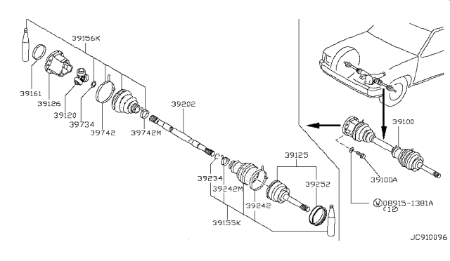
Loosen the wheel lug nuts, raise the front of the vehicle, and support it on jackstands. Remove the wheel. Remove the free-running hub, then remove the snap-ring from the axle shaft splines. The manufacturer recommends replacing the snap-ring with a new one whenever it is removed, but save the old one; it will be used for end play measurement purposes. Remove the skid plate, if equipped. Remove the axle shaft-to-axle shaft flange bolts. Have an assistant apply the brake as you loosen the bolts to prevent the axle shaft from turning. Separate the axle shaft from the axleshaft flange. Place a floor jack under the outer end of the lower control arm and raise it slightly. Separate the tie-rod end from the steering knuckle. Remove the cotter pin and loosen, but don't remove, the nut from the upper control arm ball joint. Break the steering knuckle loose from the ball joint by striking the steering knuckle boss where the ball stud passes through. Remove the nut and separate the upper control arm from the steering knuckle. Pull out on the knuckle and push the axle shaft through it, then maneuver the axle shaft out. Be careful not to stretch the brake hose and don't lose the thrust washer on the outer end of the axle shaft. For installation, inspect the needle bearing in the knuckle. If it shows signs of wear, replace it. If you install a new bearing, ensure it faces in the proper direction. Install the thrust washer on the axle shaft, if removed. The chamfer on the washer must face the center of the axle shaft. Lubricate the needle bearing in the steering knuckle with multi-purpose grease and also the axle shaft splines. Guide the axle shaft into position, pass the outer end through the knuckle, then reconnect the upper axle shaft through the ball joint to the steering knuckle. Tighten the nut and install a new cotter pin. Connect the inner end of the axle shaft to the axleshaft flange, install the bolts and tighten them. Connect the tie-rod end to the steering knuckle, tighten the nut, and install a new cotter pin. Install the snap-ring in the inner groove on the axle shaft. Using a dial indicator, measure the end play of the axle shaft in the hub. If the end play is satisfactory, remove the snap-ring, measure its thickness with a micrometer, and install a new one of the same thickness. If the end play isn't within the specified range, install a snap-ring of the proper thickness. Snap-rings are available in various thicknesses. Install the free-running hub assembly. Install the wheel and lug nuts. Lower the vehicle and tighten the lug nuts.For Pathfinder models, follow similar steps with some variations: After removing the wheel, pull off the hub cap. Before using pliers, move the cap off by driving a chisel between the cap and the drive flange, a little at a time. Remove the snap-ring from the end of the Axle Shaft, then unscrew the nuts and remove the drive flange from the hub. Remove the skid plate if present. Remove the Axle Shaft-to-axle shaft flange bolts with an assistant applying the brake. Separate the Axle Shaft from the axle shaft flange. Remove the three nuts and detach the ball joint from the control arm. Pull out on the knuckle, push the Axle Shaft through it, and maneuver it out. Be careful with the brake hose and the thrust washer on the Axle Shaft's outer end. For installation in Pathfinder models, inspect the needle bearing in the knuckle for wear, ensure the bearing's correct orientation, install the thrust washer on the Axle Shaft ensuring the chamfer faces the axle's center, lubricate the necessary parts, guide the Axle Shaft into position, and reconnect it. Ensure you connect the ball joint to the control arm, check the O-rings on the drive flange, and install the drive flange. Install the snap-ring in the groove on the Axle Shaft and measure its end play. Adjust the snap-ring if necessary, install the hub cap, and finalize with the wheel and lug nuts. Ensure the vehicle is lowered safely, and the lug nuts are tightened adequately.
Posted by NissanPartsDeal Specialist