My Garage
Cart
Make sure this part fits

Nissan A2010-8J110 Piston W/Pin

2001-2010 Nissan A20108J110

Customer Questions & Expert Answers (6)
A2010-8J110 Nissan Piston W/Pin Product Photo 1 of 2
  • Part Description
    Piston-W/Pin. This item subject to a 40% restocking fee if returned.
  • Lookup Code
    12010
  • Manufacturer
    Nissan
Make sure this part fits
$88.44 MSRP: $130.82
You Save: $42.38 (33%)
Ships in 1-2 Business Days
1
ADD TO CART
  • Related Parts
  • Product Specifications
  • Vehicle Fitment
  • Customer Questions & Expert Answers
  • Product Specifications

    BrandGenuine Nissan
    Lookup Code12010
    Manufacturer Part NumberA2010-8J110
    Part DescriptionPiston-W/Pin. This item subject to a 40% restocking fee if returned.
    Other NamesPiston
    Manufacturer NoteSTD GRADE 1
    Item Dimensions4.1 x 3.9 x 2.6 inches
    Item Weight1.30 Pounds
    ConditionNew
    Fitment TypeDirect Replacement
    ManufacturerNissan
    SKUA2010-8J110
    Shipping & ReturnShipping Policy Return Policy
    Warning: California's Proposition 65
  • Vehicle Fitment

    Year Make Model Trim & Engine Important vehicle option details
    2003-2007 Nissan 350ZBase, Enthusiast, GT, Touring|6 Cyl 3.5LVQ35DE
    2002-2006 Nissan AltimaSE, SE-R, SL|6 Cyl 3.5LVQ35DE
    2001-2008 Nissan MaximaGLE, GXEL, SE, SEL, SES, SL|6 Cyl 3.5LVQ35DE
    2003-2007 Nissan MuranoS, SE, SL|6 Cyl 3.5LVQ35DE
    2004-2010 Nissan QuestBase, S, SE, SL|6 Cyl 3.5LVQ35DE
  • Customer Questions & Expert Answers

    Q:
    Does this part fit my vehicle? Posted by NissanPartsDeal Specialist
    A:
    You can Select Your Vehicle to check if A2010-8J110 fits your vehicle.
    Posted by NissanPartsDeal Specialist
    Q:
    What steps must be taken before removing the piston and connecting rod assemblies from the engine on Nissan 350Z? Posted by Customer
    A:
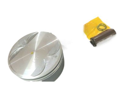
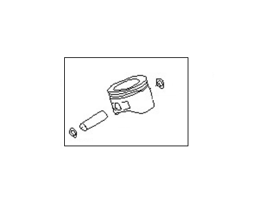
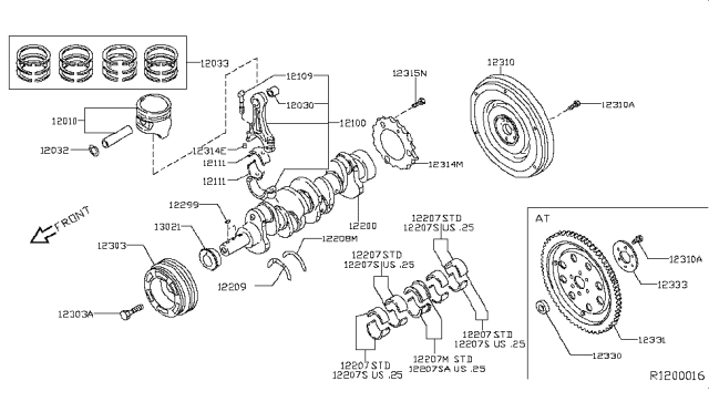
    Before the piston and connecting rod assemblies are replaced, the cylinder head and oil pan have to be in particular taken out. First check for any ridges at the upper limit of ring travel in each cylinder and, if they have not been previously ground off, they should be removed with a ridge reamer to prevent piston failure. Once the ridges are gone, orient the engine with the crankshaft vertical and measure and check the connecting rod end clearance with feelers that should fall to a specific range; if they do not, it may be necessary to replace connecting rods and pistons. Ensure you differentiate between the connecting rods and caps so that you do not confuse them; then undo the connecting rod cap bolts progressively till you can remove them by turning them with your fingers. To do so, remove the first connecting rod cap and bearing insert repeatedly and gently, and push the connecting rod and the piston assembly in the upward direction through the top of the automobiles' engine, making sure that all the ridges have been detached. Perform this for the rest of the cylinders and then place the caps and inserts back for shielding of the bearing surface. For piston ring installation make sure that the ring end gaps are correct, and the piston ring side clearance also. Place the oil control ring followed by the middle and the top rings though it is important to place the rings in the right manner. Before actually placing the piston assemblies, it is equally important that the cylinder walls and the edges in particular are thoroughly cleaned, and the crankshaft well positioned. New bearing inserts should be fitted without lubrication and should fit correctly and be positioned in the piston ring gaps. grease the piston then the rings; then, in a piston ring compressor, place the piston into the cylinder and oil the cylinder walls. Following the installation, verify the +oil clearance of the connecting rod bearing with Plastigage before fitting the cylinder and crankcase side. Always, where possible make sure the surface is clean of debris. If the clearance is out of permitted range, check the bearing sizes and the diameter of journal. Last, remove any Plastigage deposit over the bearings, relube the bearing surfaces with a grease, and tight the rod cap as in the previous process for all the assemblies, while being wary of cleanliness and orienting the thrusts in the correct form. Following that, turn the crankshaft in order to ensure that there are no signs of binding and, once again, verify the amount of end float of the connecting rod as this figure should not exceed the permissible limit.
    Posted by NissanPartsDeal Specialist
    Q:
    How to remove the piston and connect rod assemblies from an engine on Nissan Maxima? Posted by Customer
    A:
    Prior to removing the piston and connecting rod assemblies, ensure the cylinder heads, oil pan, and oil pump pick-up are removed if not already done. Use your fingernail to check for a ridge at the upper limit of ring travel, approximately 1/4-inch down from the top of each cylinder. If ridges are present due to carbon deposits or cylinder wear, they must be completely removed with a special tool according to the manufacturer's instructions, as failure to do so may result in piston breakage. After removing the cylinder ridges, turn the engine upside-down with the crankshaft facing up. Before removing the connecting rods, check the side clearance with feeler gauges, sliding them between the first connecting rod and the crankshaft throw until the play is eliminated; the side clearance should not exceed the service limit. If new connecting rods or a new crankshaft are installed, ensure the side clearance meets the specified minimum, and consult an automotive machine shop if machining is necessary. Check the connecting rods and caps for identification marks, and if they are not marked, use a small center punch to create indentations. Loosen each connecting rod cap nut by 1/2-turn until they can be removed by hand, then take off the number one connecting rod cap and bearing insert without dropping the bearing insert. Protect the crankshaft journal and cylinder wall by slipping a short length of plastic or rubber hose over each connecting rod cap bolt as the piston is removed. Remove the bearing insert and push the connecting rod/piston assembly out through the top of the engine using a wooden hammer handle, ensuring all ridges have been removed if resistance is felt. Repeat this process for the remaining cylinders. After removal, reassemble the connecting rod caps and bearing inserts in their respective connecting rods and install the cap nuts finger tight to prevent accidental damage to the bearing surfaces. Avoid separating the pistons from the connecting rods.
    Posted by NissanPartsDeal Specialist
    Q:
    How to install piston and connecting rod assemblies, including preparation, installation, and checking clearances on Nissan Maxima? Posted by Customer
    A:
    Piston/Connecting Rod Assemblies must be fitted before the following conditions are met,Cylinder walls must be clean, the top edge of every cylinder must be chamfered and crank-shaft must be positioned. Take off the cap of the number one connecting rod as you prior marked, and also wipe out the bearing surfaces by using a lint free cloth. Clean the back side of the new upper bearing insert and place it in the connecting rod, All that the tab has to be fitted outside to the recess without hammering it at all. Perform this same action for the lower bearing insert of the connecting rod on the corresponding cap; all the mating surfaces should be clean and free of oil. Align the cylinder number(s) of the piston ring gaps at necessary distance, inserted a hose to each connecting rod cap bolt, treat the piston and rings with clean engine oil and put on a piston ring compressor, with the piston skirt outside. Scribe a line across the crankshaft and turn until the number one connecting rod journal is at BDC, then lubricate the cylinder walls with engine oil. Place the piston/connecting rod assembly into the cylinder bore with the notch facing the direction of the drivebelt end: the ring compressor should bear against the block's surface. Start the connecting rod into the slot of the piston carefully and avoid any concentrated force on the pieces. Upon the completion of installation, the width of Cr-Mo connecting rod bearing oil clearance should be measured using Plastigage and the result of the crushed scaled for a proper measurement. If that is the case, ensure that clearance is tested alongside cleanliness since the diameter of the journal defines another set of bearing inserts. Oil or remove any Plastigage residue gently and spread a layer of moly-base grease or engine assembly lube on the empirical bearing seats, then replace the connecting rod and cap and tighten nuts to the appropriate measure. The same process needs to be done for the other assemblies, clean bearing inserts, make sure the right piston/rod assembly is used and lubrication of cylinder walls. Check the binding of the crankshaft after the installation while turning with your hand and measure the connecting rod end play of the crankshaft and compare it with the manufacturer's standard to ensure it is correct. If changes are to be made, seek an automotive machine shop for resizing, or a new rod if the end play is immense.
    Posted by NissanPartsDeal Specialist
    Q:
    What steps must be taken before removing the piston and connecting rod assemblies from the engine on Nissan Murano? Posted by Customer
    A:
    Before the piston and connecting rod assemblies are to be removed there are two major parts that are to be removed and they are cylinder head and oil pan. Insert your fingernail and look for any ridge at the upper limit of ring travel, which is approximately 1/4 inch down from the top of each cylinder; if there are ridges, they must be shlaped is carbon has deposited and worn into the cylinders with a ridge reamer due to the fact that it could cause piston breakage. After flattening the ridges turn the engine over so that the crankshaft is in the vertical position. Feel the end float of connecting rods with the help of feeler gauges; if the play exceeds the maximum rate, then new connecting rods may be required. Marking of the connecting rods and the caps should be done in such a way that one cannot be confused with the other. Tighten the connecting rod cap bolts progressively and uniformly, remove the cap and without letting the bearing insert drop, push the connecting rod / piston out from the top of the engine. Perform this again to the other cylinders and then replace the caps and inserts to cover not to harm them. Regarding the piston rings, measure the ring end gaps and make sure that the side clearance of the piston ring is appropriate. Locate or align the piston/connecting rod assemblies with the new ring sets, install the top ring into the first cylinder, and use the scribe-and-feeler gauges to set the end gap. If the gap is too large or too small adjust it as needed making sure not to be too forceful. Place the oil control ring followed by the middle and then the top ring with the correct orientation. It is recommended to wash the cylinder walls, sharpen the edges of the cylinder and have the crankshaft installed before installing the assemblies. Scrub the journal and bearing faces, place the new upper bearing insert, and make sure there is a snap fit without any grease. Place the gaps of the piston ring in the correct manner, apply oil to the piston as well as the rings and use a piston ring compressor for this process. After scraping the connecting rod bearing with Clean Cloth, use Plastigage to measure the oil clearance of bearing across the surfaces to mach mark. When attempting to determine the clearance, it should be noted that if the clearance is low then there could be incorrect bearing size problem or there could be some problem with the journal. Last but not the least, remove all the Plastigage deposits, coat the bearing faces with grease and put the rod cap with new nuts and bolted it with the recommended torque. The process is then continued on the other assemblies, with special attention paid to cleanliness and orientation of the components. After installation, using the special tool rotate the crankshaft to check the binding, and use a feeler blade to check the connecting rod end play once more and adjusting it if needed.
    Posted by NissanPartsDeal Specialist
    Q:
    What does corrosion in the form of small pits on the piston indicate for the 2005 Nissan Maxima? Posted by Customer
    A:
    Corrosion indicates that coolant is leaking into the combustion chamber or the crankcase. The cause must be corrected to prevent the problem from persisting in the rebuilt engine.
    Posted by NissanPartsDeal Specialist
    See expert answers on similar Piston
    If you have any questions about this product, please don't hesitate to ask us. We will be happy to help you!

Genuine Nissan Part A2010-8J110, the Right Choice

To ensure reliability, purchase Nissan part # A2010-8J110 Piston W/Pin. It can be referred to as Piston. The first option would be to use OEM parts. Designed by Nissan manufacturer and are produced with stringent factory specifications, undergoing the quality control procedures. This part fits 2003-2007 350Z, 2002-2006 Altima, 2001-2008 Maxima, 2003-2007 Murano.

NissanPartsDeal.com is a leading supplier of genuine Nissan parts and accessories, such as A20108J110 Piston W/Pin. Welcome to our vast selection of competitively priced genuine Nissan parts available online. We provide each OEM part with a manufacturer's warranty and a straightforward return policy. Place your order now and receive your parts quickly, shipped directly to your doorstep.

Why choose Nissan Parts Deal

  • Dedicated Service

    Your complete satisfaction is our #1 goal

  • Lowest Prices

    Best deals on genuine OE parts from dealerships

  • Fast Delivery

    Orders are processed and delivered promptly