×
- Hello
- Login or Register
- Quick Links
- Live Chat
- Track Order
- Parts Availability
- RMA
- Help Center
- Contact Us
- Shop for
- Nissan Parts
- Nissan Accessories
My Garage
My Account
Cart
Genuine Nissan 300ZX Transmission Assembly
Trans Assembly- Select Vehicle by Model
- Select Vehicle by VIN
Select Vehicle by Model
orMake
Model
Year
Select Vehicle by VIN
For the most accurate results, select vehicle by your VIN (Vehicle Identification Number).
37 Transmission Assemblies found

Nissan 300ZX Manual Transmission
Part Number: 32010-45P00$1875.09 MSRP: $2270.09Limited AvailabilityYou Save: $395.00 (18%)Nissan 300ZX Manual Transmission
Part Number: 32010-40P00$1875.09 MSRP: $2270.09Limited AvailabilityYou Save: $395.00 (18%)
Nissan 300ZX Manual Transmission
Part Number: 32010-19P60$1720.86 MSRP: $2243.63Limited AvailabilityYou Save: $522.77 (24%)Nissan 300ZX Manual Transmission
Part Number: 32010-30P00$1860.12 MSRP: $2251.96Limited AvailabilityYou Save: $391.84 (18%)Nissan 300ZX Manual Transmission
Part Number: 32010-54P00$2276.55 MSRP: $2756.11You Save: $479.56 (18%)
Nissan 300ZX Automatic Transmission
Part Number: 31020-X8062$3168.30 MSRP: $3835.71Limited AvailabilityYou Save: $667.41 (18%)Nissan 300ZX Automatic Transmission
Part Number: 31020-X8006$3168.30 MSRP: $3835.71Limited AvailabilityYou Save: $667.41 (18%)Nissan 300ZX Manual Transmission
Part Number: 32010-26P00$3281.23 MSRP: $3972.43Limited AvailabilityYou Save: $691.20 (18%)Nissan 300ZX Manual Transmission
Part Number: 32010-45P10$1860.12 MSRP: $2251.96Limited AvailabilityYou Save: $391.84 (18%)Nissan 300ZX Automatic Transmission
Part Number: 31020-X8020$3168.30 MSRP: $3835.71Limited AvailabilityYou Save: $667.41 (18%)Nissan 300ZX Manual Transmission Assembly
Part Number: 32010-03P03$3218.37 MSRP: $3896.33Limited AvailabilityYou Save: $677.96 (18%)Nissan 300ZX Manual Transmission Assembly
Part Number: 32010-03P01$3218.37 MSRP: $3896.33Limited AvailabilityYou Save: $677.96 (18%)
| Page 1 of 2 |Next >
1-20 of 37 Results
Nissan 300ZX Transmission Assembly
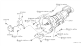
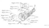
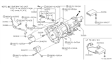
The Transmission Assembly of Nissan 300ZX directs the torque of the engine to the wheels such that the sports car can accelerate smoothly on city streets or winding highways. During its lifecycle, the driver experienced two principal styles of Transmission Assembly, a conventional manual and a hydraulic automatic, each chosen to strike a balance between control and convenience. The gears in the manual Transmission Assembly are arranged in parallel shafts and can be locked together by the driver using a shifter. Therefore, the engine speed can be raised for quick launches and lowered for economical cruising. The automatic Transmission Assembly utilizes planetary gearsets and pressurized fluid under the control of an onboard controller to automatically change gears without a clutch pedal. Both setups direct torque, but the manual one is great for enthusiasts who can grab the gear they want. The automatic does more relaxed commuting, and in stop-and-go traffic, it reduces fatigue. Nissan kept gear synchronizers in the manual to smooth shifts and prevent crunching. Besides, the brand tuned gear ratios so every 300ZX could climb steep hills without straining the engine yet still cruise efficiently at highway pace. Nissan collectors acknowledge today that the 300ZX's high power coupled with drivability is a function of a robust Transmission Assembly.
If you need any OEM Nissan 300ZX Transmission Assembly, feel free to choose them out of our huge selection of genuine Nissan 300ZX Transmission Assembly. All our parts are offered at unbeatable prices and are supported by the manufacturer's warranty. In addition, we offer quick shipping to have your parts delivered to your door step in a matter of days.
Nissan 300ZX Transmission Assembly Parts Questions & Experts Answers
- Q: How to overhaul the Transmission Assembly on a FS5W71C manual transmission for a Nissan 300ZX?A:With the transmission removed, thoroughly clean the external surfaces and remove the rubber dust boot from the withdrawal lever opening in the clutch bellhousing. Take out the release bearing and hub along with the withdrawal lever, then remove the reverse lamp switch, neutral switch, top gear switch, or overdrive gear switch as equipped. Detach the screw retaining the speedometer gear to the rear extension housing and lift out the gear. Pry off the E-ring from the stopper guide pin and drive out the pin, followed by removing the return spring plug and lifting out the return spring and plunger. Remove the two screws retaining the reverse check cover to the housing and lift out the reverse check sleeve. Detach the bolts and drive the rear extension housing from the main transmission casing using a soft mallet, then remove the front cover retaining bolts and take off the front cover with gasket, extracting the countershaft bearing shim and the input shaft bearing snap-ring. Drive off the one-piece bellhousing/transmission casing from the adapter plate, using a soft face hammer while holding the exposed rear shaft. Create a suitable plate to bolt to the transmission adapter or purchase a tool from Nissan to support the adapter in a vise. Drive out the securing pins from each of the shift forks and remove the three check ball plugs. Withdraw the selector rods from the adapter plate, catching the shift forks and extracting the balls and springs as the selector rods are withdrawn, noting that the four smaller balls are the interlock balls. Inspect the gears and shafts for any wear, chipping, or cracking, and use a feeler gauge between each mainshaft gear to determine the amount of gear end play, comparing the results to the specifications. If the gear end play is not within specifications or if the gears or shafts show signs of wear or damage, disassemble the gear assemblies and replace the defective parts. Lock the gears and use a two-leg puller to draw the front bearing from the countershaft, then extract the now exposed snap-ring from the countershaft. Withdraw the countershaft gear together with the input shaft, taking care not to drop the needle roller bearing located on the front of the mainshaft. Extract the snap-ring from the front of the mainshaft, followed by the thrust washer, and withdraw the third and fourth synchronizer unit, followed by third gear. Both the mainshaft nut and the countershaft nut are staked to prevent loosening; use a hammer and punch to drive out the staking and remove the countershaft nut, which should not be reused. Use a gear puller to remove the countershaft overdrive gear and bearing, then remove the reverse counter gear and spacer. Remove the snap-ring from the reverse idler shaft and the reverse idler gear, followed by the snap-ring retaining the speedometer gear to the mainshaft, then remove the speedometer gear and steel ball. Remove the two snap-rings from behind the speedometer gear and withdraw the overdrive mainshaft bearing. Drive out the staking on the mainshaft nut and remove it, ensuring this nut is not reused. Remove the thrust washer, overdrive gear bushing, needle bearing, overdrive gear, reverse main gear, overdrive synchronizer assembly, and insert retainer. Drive the mainshaft and countershaft assemblies simultaneously from the adapter plate using a soft-faced hammer. Carefully examine the gears and shaft splines for chipping of the teeth or wear, then dismantle the gear train into its component parts, replacing any worn or damaged items. Examine the shaft for scoring or grooving and the splines for twist, taper, or general wear. Inspect the synchromesh units for cracks or wear and replace them if evident, particularly if there has been a history of noisy gear changes. Press the baulk ring tight against the synchromesh cone and measure the gap between the two components; if it is less than specified, replace the components. When reassembling the synchromesh unit, ensure that the ends of the snap-rings on opposite sides of the units do not engage in the same slot. Begin assembly of the mainshaft by installing the second gear needle bearing, second gear, the baulk ring, followed by the first/second synchromesh unit, noting the direction of installation. Install the first gear baulk ring, needle bearing, steel ball, thrust washer, bushing, and first gear, ensuring the steel ball is well greased. The countershaft front bearing was removed during the dismantling process, while the rear bearing remains in position in the adapter plate. Withdraw the countershaft drive gear and extract the two Woodruff keys, checking all components for wear, especially the gear teeth and shaft splines for chipping. Reinstall the Woodruff keys and the snap-ring, with reassembly being a reversal of dismantling. Remove the snap-ring and spacer from the input shaft, then withdraw the bearing using a two-leg puller or a press, discarding the bearing once removed. Press the new bearing onto the shaft, applying pressure to the center race only, and reinstall the washer. Several thicknesses of snap-rings are available for the main input shaft bearing; choose a size that will eliminate bearing end play. Pry out the oil seal from the rear extension and drive in a new one with the seal lips facing inwards, then reinstall the speedometer pinion sleeve O-ring seal. Reinstall the oil seal in the front cover by prying out the old one and driving in a new one with an appropriately sized socket. Loosen the nut on the end of the striking rod lock pin until it is half off the threads, then use the nut as a guide to drive the lock pin from the striking rod with a punch. Slide the striking lever from the striking rod and withdraw the rod from the rear of the housing, checking the rod and lever for wear or damage and replacing if necessary, along with the O-ring on the striking rod. Inspect the bushing in the rear of the extension housing; if worn or cracked, the entire rear extension housing must be replaced. Reinstall the striking rod assembly by reversing the removal procedure. Before beginning to reassemble, remove, examine, and replace if worn the mainshaft and countershaft adapter plate bearings by unscrewing the six screws retaining the bearing retainer plate to the adapter plate, likely requiring an impact driver. With the bearing retainer plate removed, press the mainshaft and countershaft bearings from the adapter plate, applying pressure only to the outer races. Check the bearings for wear by washing them in clean solvent and drying in air; spin them with fingers, replacing if noisy or loose in operation. Ensure the dowel pin and oil gutter are correctly positioned on the adapter plate, tapping the mainshaft bearing lightly and squarely into position. Drive the reverse idler shaft into the adapter plate so that two-thirds of its length projects rearwards, ensuring the cutout in the shaft is positioned to receive the edge of the bearing retainer plate. Install the bearing retainer plate and tighten the screws to specifications, staking each screw in two places to prevent loosening. Tap the countershaft rear bearing into position in the adapter plate, then press the mainshaft assembly into position in the bearing, supporting the rear of the bearing center race during this operation. Press the countershaft assembly into position in the bearing, again supporting the rear of the bearing center race. Install the needle bearing, third gear, baulk ring, and the third/fourth synchromesh unit onto the front of the mainshaft, followed by the thrust washer and selecting a snap-ring from the sizes. Insert the needle pilot bearing in its recess at the end of the input shaft, mesh the countershaft drive gear with the fourth gear on the input shaft, and push the drive gear and input shaft onto the countershaft and mainshaft simultaneously using Nissan tools or a piece of tubing to drive the countershaft gear into position while supporting the rear of the countershaft. Select a countershaft drive gear snap-ring from the sizes to minimize gear end play, then use a socket to drive the front bearing onto the countershaft. Install the reverse counter gear spacer onto the rear of the countershaft, followed by the snap-ring, thrust washer, needle bearing, reverse idler gear, reverse idler thrust washer, and rear snap-ring onto the reverse idler shaft. On the rear side of the mainshaft, install the synchronizer assembly, reverse gear, overdrive gear bushing, needle bearing, and baulk ring, then install the reverse counter gear on the countershaft. Mesh the overdrive gear with the overdrive counter gear and install them on their respective shafts, applying grease to the steel ball and installing it along with the thrust washer onto the rear of the mainshaft. Install a new locknut onto the rear of the mainshaft and torque it to specification, using a wrench adapter to ensure accurate tightening. Install the countershaft rear end bearing onto the countershaft, followed by the countershaft locknut, torquing it to specification. Use a hammer and punch to stake both the mainshaft and countershaft locknuts so they engage the grooves in their respective shafts, then measure the gear end play again. Fit a snap-ring onto the mainshaft and install the overdrive mainshaft bearing, choosing a snap-ring from the sizes to eliminate end play of the mainshaft rear bearing. Install the next snap-ring, grease the steel ball, and install it along with the speedometer drive gear onto the mainshaft, followed by the last snap-ring. Locate the first/second shift fork onto the first/second synchronizer unit, ensuring the long end of the shift fork is towards the countershaft, and locate the third/fourth shift fork onto the third/fourth synchronizer unit with the long end opposite to the first/second shift fork. Position the overdrive reverse shift fork onto the overdrive synchronizer so that the upper rod hole aligns with the third/fourth shift fork. Slide the first/second selector rod through the adapter plate and into the first/second shift fork, aligning the hole in the rod with the hole in the fork and driving in a new retaining pin. Align the notch in the first/second selector rod with the check ball bore, then install the check ball and spring and screw in the check ball plug with thread sealant applied. Invert the adapter plate assembly while holding the third/fourth and OD/reverse shift forks in position, dropping two interlock balls into the third/fourth detent ball plug hole and pushing them against the first/second selector rod. If positioned correctly, the interlock balls will drop into place. Slide the third/fourth selector rod through the upper hole of the OD/reverse shift fork and the adapter plate, ensuring the interlock balls are held between this selector rod and the first/second selector rod, then into the third/fourth shift fork. Align the holes in the shift fork and selector rod, driving in a new retaining pin, and install a check ball, spring, and check ball plug with thread sealant to the third/fourth check ball plug bore, ensuring the notch in the third/fourth selector rod aligns with the check ball plug bore before assembling the check ball. Drop two interlock balls into the remaining ball plug bore, ensuring they locate against the third/fourth selector rod, then slide the overdrive/reverse selector rod through the overdrive reverse shift fork and into the adapter plate, ensuring the two interlock balls are held in position between the third/fourth selector rod and the overdrive/reverse selector rod, sliding the overdrive/reverse selector rod into the adapter plate until the notch aligns with the check ball plug bore. Insert the check ball, spring, and check ball plug as before, driving in a new retaining pin to retain the overdrive/reverse shift fork to the overdrive/reverse selector rod. Tighten the three detent ball plugs to the specified torque, thoroughly oil the entire assembly, and check that the selector rods operate correctly and smoothly. Clean the mating faces of the adapter plate and the transmission casing, applying gasket sealant to both surfaces, then tap the transmission casing into position on the adapter plate using a soft face hammer, ensuring it engages correctly with the input shaft bearing and countershaft front bearing. Fit the outer snap-ring to the input shaft bearing, clean the mating faces of the adapter plate and rear extension housing, and apply gasket sealant. Arrange the shift forks in their neutral mode and lower the rear extension housing onto the adapter plate, ensuring the striking lever engages correctly with the selector rods. Fit the bolts securing the sections of the transmission together and tighten them to the specified torque. Measure the amount by which the countershaft front bearing protrudes from the transmission casing front face using feeler gauge blades, then select the appropriate shims. Install the shim using a dab of thick grease, then fit the front cover to the transmission casing within the clutch bellhousing, complete with a new gasket, taking care not to damage the oil seal as it passes over the input shaft splines. Tighten the securing bolts to the specified torque, ensuring the bolt threads are coated with gasket sealant to prevent oil seepage, and complete the reassembly by reversing the earlier procedures.

Related Nissan 300ZX Parts
 Nissan 300ZX Torque Converter
 Nissan 300ZX Valve Body
 Nissan 300ZX Needle Bearing
 Nissan 300ZX Transmission Pan
 Nissan 300ZX Transmission Oil Cooler
Browse by Year
1996 Transmission Assembly 1995 Transmission Assembly 1994 Transmission Assembly 1993 Transmission Assembly 1992 Transmission Assembly 1991 Transmission Assembly 1990 Transmission Assembly 1989 Transmission Assembly 1988 Transmission Assembly 1987 Transmission Assembly 1986 Transmission Assembly 1985 Transmission Assembly 1984 Transmission Assembly